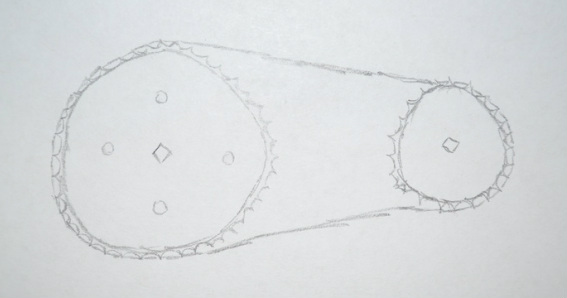
Chain and sprocket
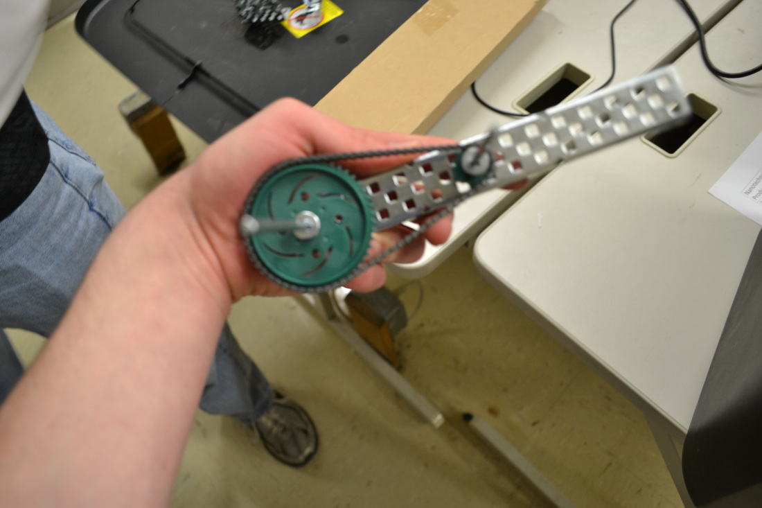
This is an example of a chain and sprocket. This is a recognizable gear since these are used on bicycles. All that is needed is two gears on axles and a chain to connect them. On bikes they are man power but a motor can also be attached to power it.
VW Project
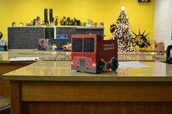
This here, it is firetruck. This was designed to fulfill the competition requirements in the Virginia Western robot competition. In the competition, we were tasked in picking up 12 golf balls on an enclosed course autonomously.
Robot Chassis
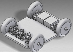
This is the basic design for the robot chassis that was enclosed inside the walls.
The picture was created by Kevin Cox.
The picture was created by Kevin Cox.
Design Evolution
When given the task, we decided it would be cool if we could base our robot around a fire truck. We knew we could use the same body as a fire truck and were planning on attaching the claw at the end of the ladder that was to be attached to the top and operate as a normal ladder would. After identifying that a real ladder would cost too much, it was decided that we could keep the look of a fire truck by using a ladder that is mounted on the side like they used in the olden days. when we attached the claw on the side, it was not high enough to drop the ball in the box. To fix this problem, we attached the ladder to a pulley system. we intended for the saws of life and a flamethrower to be on it for defense but creativity was put in a choke-hold by Mrs. Gerrol (and then choke slammed it but i digress).
Fabrication Methods
When building the robot, we started with the chassis. on the chassis, the basic outline was reached in order to allow room for the wheels. after that, the motors were attached at the rear. next, our resident car guy informed independent axles in the front would enable a better turning radius. so did that. then, the shell of the fire truck was designed and put on. After this, the ladder was build and a claw design was found. The claw was built and then attached to the ladder. After seeing the claw was not high enough to drop the balls into the box, a pulley system was design to raise the claw.
Materials
We used four motors (two normal motors and two servo motors), angle bars. Four wheels were used to make the robot move. wood was used as the base and walls. Gears were used to turn the claw. Metal bars with holes were used to make the claw. Metal bars were used to connect the wheels to the motor. String was used as a pulley system to lift the claw.
Below of the picture of the programming used to operate the robot. The programming used simple commands such as a start command, commands to run certain motors at a certain power and for how long, and also a finish code.

The competition was fun to compete in, but it was hard to work around the money limit as well as the limited amount of resources. If I was to redo this, I would use a front end loader for the balls that would use an elevator system to put the balls in the box.
Robot
In making the robot, we started by making the chassis. To make the chassis we took an angle bar, chassis bars, and a chassis bumper and attached them with screws and keps nuts. Next, we made the drive train. In making the drive train, we attached a motor on each side and used gears to make the tires turn. We put a stabilizing wheel on the front. Finally, we added the controller the can be operated both with a cord and without a wire. We put a plate on to protect the battery that was attached to the bottom side.


When operating the robot, there are two control options: Tank and Arcade. When operating in tank mode, one must use both control sticks to maneuver the robot. When using arcade mode, only the left control stick is needed.
In the video, we show the operation of the robot going between three stools and the turn radius.
